Contact us
Get in touch with our experts to find out the possibilities daily truth data holds for your organization.
Persistent Monitoring
Natural catastrophe solutions
08 November 2024 | Earth Observation,Data,Missions
16 min read
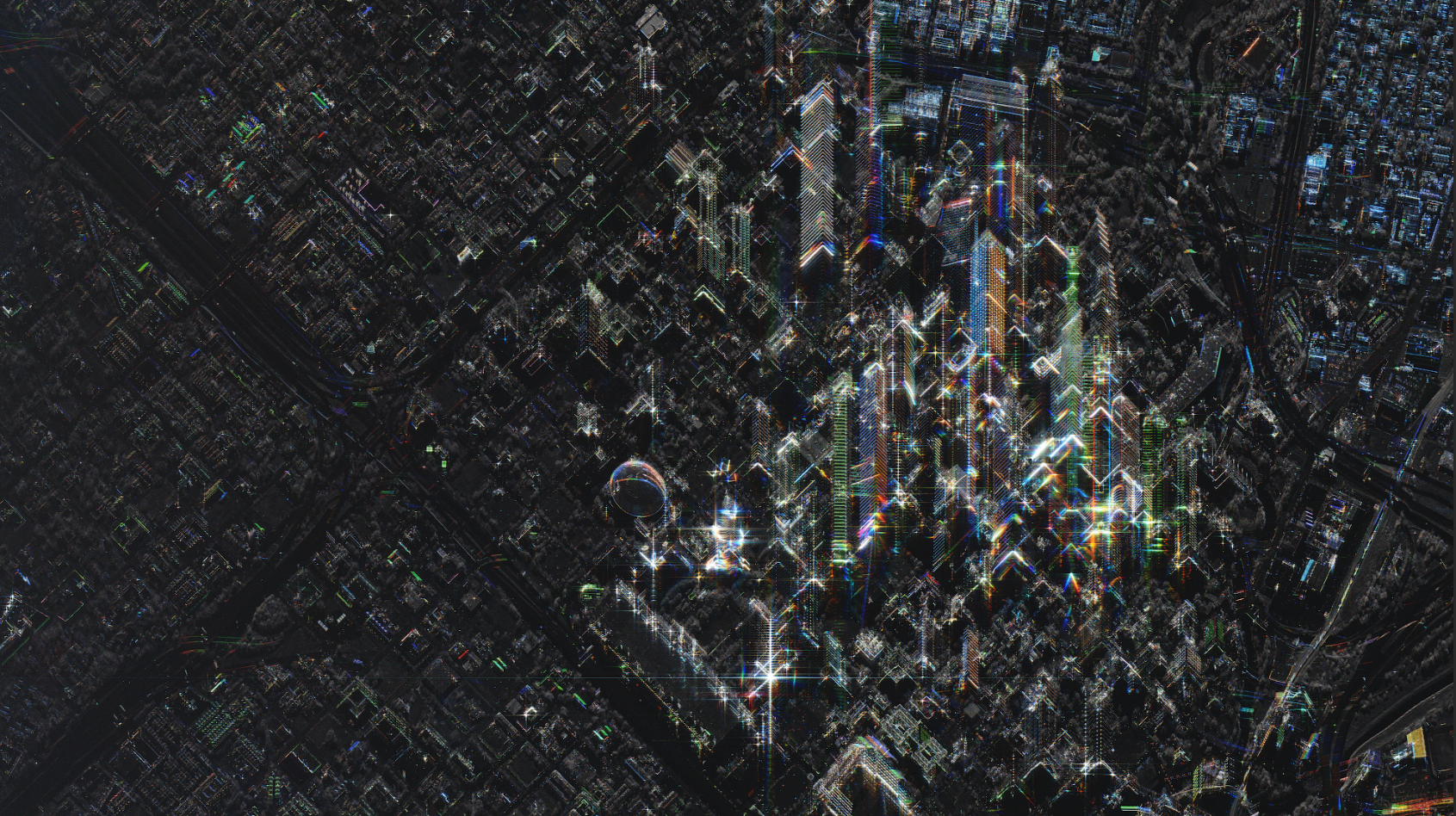
SAR images differ from the images we are used to in two important ways:
These two differences produce some unfamiliar effects, which human brains (conditioned to process visual wavelengths) can struggle to make sense of. To correctly interpret SAR images, we need to relearn how to look based on our understanding of these special phenomena.
In this blog post we'll explain what makes SAR different by taking a closer look at :
How a pixel appears in a SAR image is partly determined by how the radar pulse reflects off objects on the ground. Pulses reflect in many directions. The more energy that makes it back to the antenna, the ‘stronger’ the reflection. Strong reflections produce bright pixels in the image; weak reflections produce dark pixels.
Let’s imagine we are creating an image of Washington, DC. When our radar pulse hits the reflecting pool in front of the Lincoln Memorial, the water will reflect the energy away from the sensor in what is called specular reflection (from the Latin word speculum meaning ‘mirror). This means the water in the image will be represented by dark pixels.
When the pulse hits an object with more structure, such as the lawn by the side of the reflecting pool, we get what’s called a diffuse reflection, which produces a gray pixel. The same would happen if the pulse were to hit the trees that line the lawn because the energy would get displaced among the branches.
But what if the pulse were to hit the ground near the memorial itself? Well, then the energy would bounce up against the side of the building and reflect directly back up to the sensor. This is called a dihedral reflection, and it produces a bright, white pixel.
There is also something called a trihedral reflection, which is when a pulse hits the corner of a cuboid structure, again reflecting directly back to the antenna and giving us a very bright, white pixel. This is extremely important for the interpretation of SAR images because nature does not tend to create structures that are cuboid. It follows that a bright, glinting reflection on SAR will almost always indicate a human-made object.
To see some of these principles in action, take a look at the SAR image below of an airport in Germany. You’ll notice that the runways show up very dark (due to specular reflection) and that the grassy sections are grayer (due to diffuse reflection) while the airport buildings and infrastructure are the brightest parts of the image.
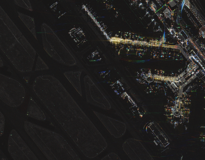
The runway shows up very dark, and the buildings are the brightest in this Dwell Precise CSI image of an airport in Germany.
Objects on the ground react to electric fields in different ways. The extent to which an object reflects an electric field is known as the dieletric constant – and the higher that value is, the stronger the reflection is. Here are the values of the dielectric constant for a few common states and materials:
| STATE/ MATERIAL | DIELECTRIC CONSTANT |
| Vacuum | 1 |
| Air | 1 |
| Dry soil | 5 |
| Wet soil | 25 |
| Water | 80 |
| Metal | 80 |
A high dieletric constant means strong reflectance, which is why metal objects such as oil derricks and large metal ships show up so brightly on a SAR image.
You may be wondering at this point why water shows up dark. The reason is because although the water does strongly reflect the radar energy, it reflects it away from the SAR antenna.
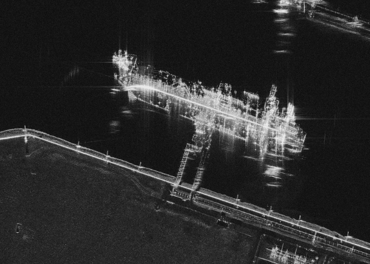
The cargo ship shows up very brightly in this SAR Dwell Precise mode image.
When an object, such as a mountain, blocks a SAR illumination, the area of ground in ‘shadow’ appears completely black in the image. The reason this happens with radar illumination but not with sunlight is because sunlight, unlike radar, is scattered in the earth’s atmosphere. (Shadows on the moon, where there is no atmosphere, are black.)
Shadows can be useful when interpreting a SAR image. In the Dwell Precise mode image of the Boneyard in Tuscon, Arizona below, for example, the shadows formed by the wings of the plane make the aircraft easy to identify.
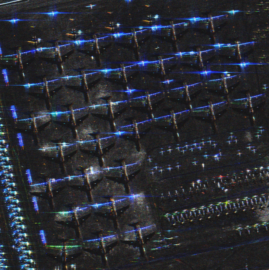
Shadows formed by the wings of the planes make them easier to identify.
Each pixel in a SAR image represents an area of ground of equal range from the antenna. However, not all areas of ground are made the same. The illustration on the left below shows pulses moving from antenna to ground, with each curve representing an area where the range is the same (we call this the arc of equal range). As you can see, the structure of the hill means that its near slope all falls within the same range ‘bin’. This means it will be represented by a single pixel. The far side of the hill, however, will be represented by several pixels because it has different range values. This creates a foreshortening effect in the final image.

The near slope has one range value whereas the far side has several.
In pixel terms, this means the near slope will look smaller than it really it is.
You can see this effect for real in the SAR image of Mount Taranaki, a New Zealand stratovolcano, below. The front slope of the mountain is represented by a small number of very bright pixels while the rear slope is represented by a much larger number of darker pixels.
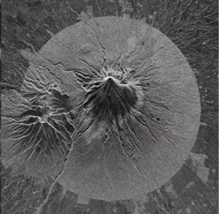
Early SAR image of Mount Taranaki, New Zealand
We saw just now how two different points on the earth’s surface can have the same range due to elevation. This produces an effect called layover, where the top of a mountain, hill or manmade structure occupies the same pixel location as the area of ground in front of it.
Layover always happens with elevated objects – and its direction is always towards the antenna, perpendicular to the flight path.
You can see layover occurring in the magnified area of the image below, where the mountain peaks extend over the area depicted above them. They extend upwards in the image because the top of the picture is where the energy is coming from (i.e. the flight path of the antenna).
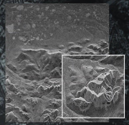
Early SAR image of Mount Taranaki, New Zealand
Interestingly, this effect also happens on oblique optical images, where it is referred to as ‘relief displacement’.
One, slightly strange SAR effect that you do not get with optical images can be seen in the airfield picture of Kirtland Air Force Base below.
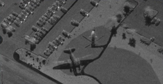
The ground appears to be visible through the wings due to an effect called superimposition of pixels. Image courtesy of Sandia National Laboratories.
You will notice if you look closely that the ground appears to be visible through the plane’s wings, as if they were partially transparent. This is due to an effect called the superimposition of pixels.
The image below illustrates what is happening here. As you can see, the energy in the arc of equal range is interacting with different objects in different ways. Some of it is hitting the plane’s wing causing specular reflection (a dark pixel), while some of it is hitting the grass causing diffuse reflection (a light pixel). The fact that the two reflections have the same range means they are combined in the image, giving us a medium reflection (a gray pixel). This creates an appearance of partial transparency.
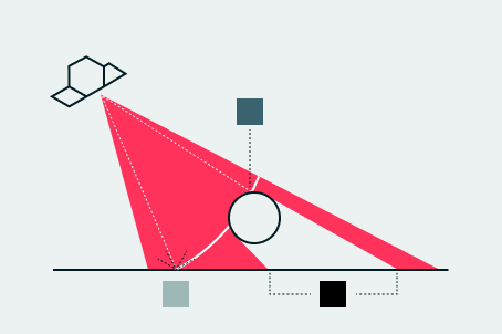
Superimposition of pixels: specular reflection (dark) pixel), diffuse reflection (light pixel), medium reflection (gray pixel).
Moving objects are displaced in SAR images. In other words, they appear in a slightly different location to where they actually were when the data was collected. How they are displaced depends on their direction of movement in relation to the flight path.
Objects traveling perpendicular to the flight path cause a Doppler shift, which displaces the object to the right in the image (if it is moving towards the flight path) or to the left (if it is moving away from it). Objects traveling parallel to the flight path are elongated (if they are moving in the same direction as the antenna) or shortened (if they are moving in the opposite direction).
In reality, of course, the traveling object is rarely completely perpendicular or completely parallel, so you actually get a combination of two displacement effects.
You can see the displacement effect clearly in the SAR image of Washington, DC below. The ellipses highlight the signatures of two trains, both of which have been displaced in the image. The train to the left of the image has been displaced to the right relative to the flight path, which means it was moving towards the antenna. The train to the right of the image has been displaced to the left relative to the flight path (the bridge it was crossing is visible directly above it), which means it was moving away from the antenna.
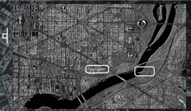
Displacement effect: the train to the left has been displaced to the right relative to the flight path. The train to the right of the image has been displaced to the left relative to the flight path.
It is often said that interpreting SAR images is complicated. We beg to disagree. The way we see it, interpretation is not difficult – just different. To do it correctly, you need to relearn some of your visual-wavelength instincts and apply a new selection of viewing principles that are unique to SAR.
23 January 2026
Federation: The next step in space-based ISR
Director of Product Management Udo Szabo explains how the federated model evolved from an idea into...
Read more about Federation: The next step in space-based ISR →06 November 2025
Beyond the Echo - How satellites steer the radar beam
Shikha Sharma and Leszek Lamentowski reveal the technology behind ICEYE SAR satellite agility.
Read more about Beyond the Echo - How satellites steer the radar beam →27 June 2025
Beyond the Echo - Rapid-fire imaging, on repeat
Shikha Sharma and the ICEYE team explore physical maneuver, electronic beam steering, and optimized...
Read more about Beyond the Echo - Rapid-fire imaging, on repeat →