Contact us
Get in touch with our experts to find out the possibilities daily truth data holds for your organization.
.jpg?width=64&name=pekka-author%20(1).jpg)

By reaching a SAR image resolution of 25 cm with small satellites, ICEYE sets a new standard in terms of stability and precision of small satellite systems and accurate SAR image processing. With this very high-resolution imaging capability of 25 cm, ICEYE data achieves the same resolution class as provided by conventional SAR satellites operating at their highest performance.
This technical blog post gives an introduction to SAR image resolution, which differs from other remote sensing imaging data.
The resolution of a radar image refers to the ability to distinguish (i.e. resolve) between features that are very close together. During image acquisition, all radar pulses reflected from each feature on the ground are received by the antenna and registered. In data processing these pulses are used to build the image scene. This can be done with arbitrary sample spacing, but the resolution defines how well we can separate different point scatterers from each other. This ability depends on the bandwidth of the signal, and in the following we explore what that actually means.
In the case of SAR images, there are two separate dimensions of measurement: the flight direction of the sensor, called azimuth, and the look direction, which is perpendicular to the flight direction and called range. The available bandwidth and thus resolution for either of these dimensions is dependent on different parameters, so we will cover them separately in the following two chapters.
Most radar systems use ‘chirped’ signals. Instead of sending short pulses with a constant frequency, long pulses are transmitted that sweep up or down in frequency (hence the term chirp). The extent of the frequency sweep is known as the pulse bandwidth or radar bandwidth. After data acquisition, the known frequency sweep can be used to compress the energy in the long pulses into shorter pulses that appear brighter in the final image. In digital signal processing terms, this is cross-convolution of the sampled received signal with the generated reference signal. The ‘half-power width’ of the resulting compressed pulses is known as the range resolution and is dependent on the bandwidth of the transmitted pulse. The digital sampling rate of the system needs to be high enough to satisfy the Nyquist requirement for recording the full signal bandwidth. But adding more sampling rate will not increase the range resolution, even if the sample spacing decreases.
The time it takes a pulse to be reflected from the ground back to the radar sensor is precisely measured and, as the speed that the pulse travels is constant (the speed of light), the distance traveled by the pulse can be calculated. This direct measure of range from the sensor to a scatterer location is known as the slant range.
The radar image is formed by recording samples over a range window. This is the time (and therefore distance) for recording each pulse. Radar sensors don’t have enough memory to constantly record so the data recorder is opened to only listen to the reflection from the part of the ground of interest. This opening to the pulse echoes is called the range window and occurs once for every pulse. These recorded samples are evenly spaced and the length of the range window determines the size of the image in the range direction.
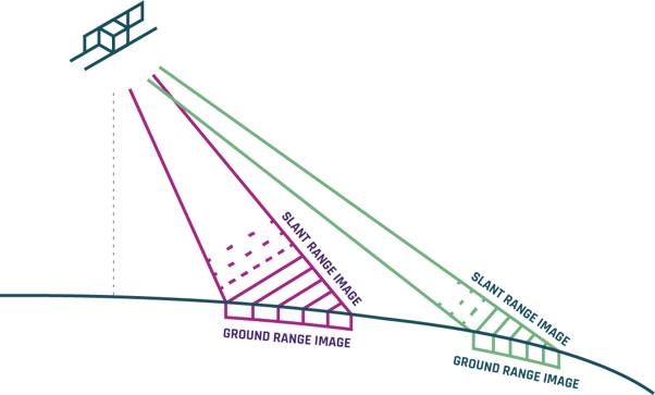
Figure 1. Ground range image size changes with the incidence angle.
It can be seen from Figure 1 that the size of the collected image on the Earth’s surface varies with imaging geometry. If the same range window size is used, then the image size on the ground will be larger when the incidence angle is smaller. It can also be seen that the Earth’s curvature causes the ground samples to have different lengths when the slant range samples are uniformly spaced. These effects make the SAR image appear distorted when looked at in this ‘native’ collection geometry. To make the images appear to represent the actual ground, a slant-range to ground-range transformation is applied. After this transformation, the ground range geometry represents the true horizontal distance between objects on the ground.
A consequence of this transformation is that the ground range resolution becomes finer at larger incidence angles as the slant range becomes more aligned with the ground. In the extreme case where the incidence angle is 90 degrees, the ground range resolution would be equal to slant range resolution.
In a basic (non-SAR) radar system, the azimuth resolution depends purely on the length of the antenna aperture: the longer the antenna, the narrower the radar beam is and the finer the resolution (the ability to tell two scatterers apart from each other) becomes. Since the length of a real-aperture radar antenna has physical and technological limits, the so-called synthetic-aperture radar (SAR) was developed.
SAR systems synthetically increase the antenna size by using the forward motion of the satellite during acquisition. As the satellite passes a certain area, thousands of pulses are transmitted and reflected back to the sensor sequentially. By recording and combining the individual pulses, a ‘synthetic aperture’ is created in the SAR image formation processor which results in a significantly improved azimuth resolution.
The image formation processor uses the Doppler effect, caused by the radar’s motion past a scene, to focus the signals during the azimuth processing. The area on the ground is illuminated by the radar beam with several pulses during a satellite pass. When the moving beam is in the direction towards a scene, the Doppler shift is positive since the distance between the sensor and the scene is decreasing. By the time the antenna is at the side of the scene, the received Doppler shift is zero. After that, the Doppler shift becomes negative as the satellite is moving away from the scene.
The azimuth resolution of a synthetic aperture system is dependent on the total extent of these Doppler shifts, called the Doppler bandwidth. In a similar way to the range resolution, the azimuth resolution is determined by the size of this bandwidth. In order to achieve the finest resolutions, a spotlight mode is used. In this collection mode the satellite adjusts its beam pointing to illuminate a single location on the ground for a longer duration. This extends the amount of energy and Doppler bandwidth collected from the scene.
Conversely from the range dimension, where slant and ground resolutions are different depending on the incidence angle, in the azimuth dimension there are only small incidence angle effects, the azimuth resolution in the ‘native’ slant plane converts directly to the ground plane with no meaningful change in resolution.
Having described how the range and azimuth resolutions are achieved, the new demonstrated Spotlight imaging mode by ICEYE can be discussed.
The new imaging mode uses 300 MHz of bandwidth in the transmitted chirp. This provides a slant range resolution of 0.5 m. The equation for slant range resolution δr is calculated by dividing the speed of light (c) by twice the bandwidth (B): δr = c/(2B). As the bandwidth that a radar transmits is constrained by the RF (radio frequency) design and frequency licences, the maximum bandwidth is difficult to change.
The azimuth resolution can be freely manipulated however, provided that you have a satellite that is agile enough to form a spotlight on the scene for long enough. The new ICEYE mode exploits ICEYE’s small satellite agility to form a synthetic aperture of approximately 10 seconds to provide an azimuth resolution of 25 cm.
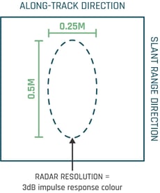
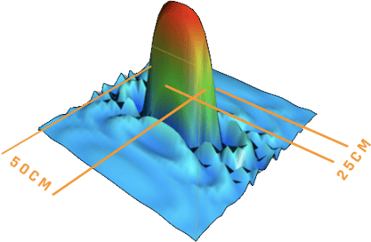
Figure 2. Radar resolution is measured as the width of the system’s ‘impulse response function’.
The discussion so far has considered only the resolution of the system. In the optical world this is often the same as the size of a pixel in the final image - something called the ‘ground sample distance’ or GSD. For radar this is slightly different. In order to take full advantage of the resolution of a collection, the SAR processor needs to reduce the pixel size so that it is smaller than the resolution. This is so that two objects close together can be resolved as two different objects. If the pixel was the same width as the resolution then no dark ‘trough’ would be identifiable between the two ‘peaks’ of objects and they would appear as only one object.
Because of this requirement the new Spotlight mode has a native pixel spacing that is finer than the resolution (typically 0.125 m in azimuth and 0.25 m in range). Whilst this product preserves the integrity of the collected data which is useful for scientific exploitation, the files can be very large and visually unappealing to those used to exploiting optical imagery.
A more typical image representation of this type of collection mode is found in our GRD (Ground Range Detected) product. This product takes the slant range representation and performs the slant-range to ground-range image translation. In performing this, the pixels are made to have a square aspect ratio on the ground, usually 1 m by 1 m, by averaging adjacent pixels together. In addition to making a more map-like image product, the process of averaging, usually called multi-looking, reduces noise-like speckle from the image and significantly improves the overall image quality. As the pixel size is now larger, but the area covered by the image is the same, the final file size is smaller.
ICEYE continues to provide a standard high resolution Spotlight mode image product that is collected with 2 seconds of integrated illumination time, yielding approximately 1 m azimuth resolution. In both, the new mode and the original mode, the range resolution remains the same.
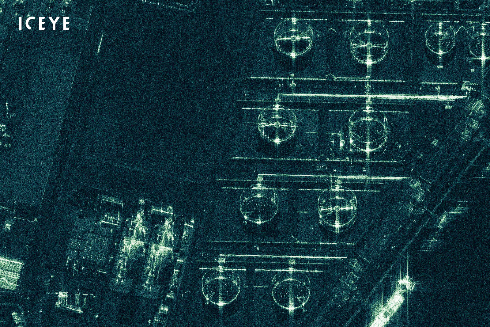
Figure 3. Floating roof oil tanks in Port of Rotterdam, The Netherlands.
The 25 cm resolution mode provides a useful capability for tasks that require very precise measurements to be used. An example can be found in Figure 3 which is of an oil storage facility in Port of Rotterdam in the Netherlands. In this task the challenge is to determine the precise height of the floating top lids on the oil tanks so that the volume of their contents can be measured. This involves the precise measurement of scattering points around the rings that are observed in the radar image from the top of the tank and the floating lid.
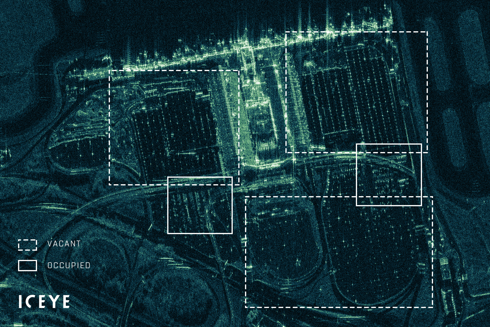
Figure 4. Terminal and parking lots at Hartsfield-Jackson Atlanta International Airport, Georgia, US.
This example shows the exceptionally empty parking lots at the Hartsfield-Jackson Atlanta International Airport in Georgia, US. Imaging in very high-resolution allows differentiating between individual cars for accurate counts. As you can see in Figure 4, distinguishing cars from other small metal structures like lamp posts and railings is still a non-trivial task, which is a topic for another post. But the high-resolution certainly makes the detection and count easier when the scatterers don’t blur to each other.
After this initial demonstration the next step will be to calibrate the product and develop the user documentation for it. We want to get the new mode available to the community as soon as possible, certainly within the next few months. The images will be delivered in the standard format of our image products and will therefore be compatible with most standard GIS tools.
Please stay tuned for announcements on feature releases. Until then, check out our latest data samples of high-resolution Spotlight imagery. Sample datasets are available for free download.
Download 


03 June 2026

23 January 2026

06 November 2025